Particles & dust
Metals, minerals and organic materials can produce fine or ultrafine particles, oxides, soot and solid residues that must be characterized.
NWS Laser EXPERTISE · FUMES & PARTICLES
Marking, engraving and cutting alter the material. Before defining a solution, the material, coating, laser technology and production parameters that determine emissions must be qualified.
THE CHALLENGE
Laser fumes can include ultrafine particles, dust, gases, vapors and organic compounds. Their composition depends on the processed material, its fillers or coatings, the wavelength, the deposited energy and the production cycle.
SEE THE PROCESS
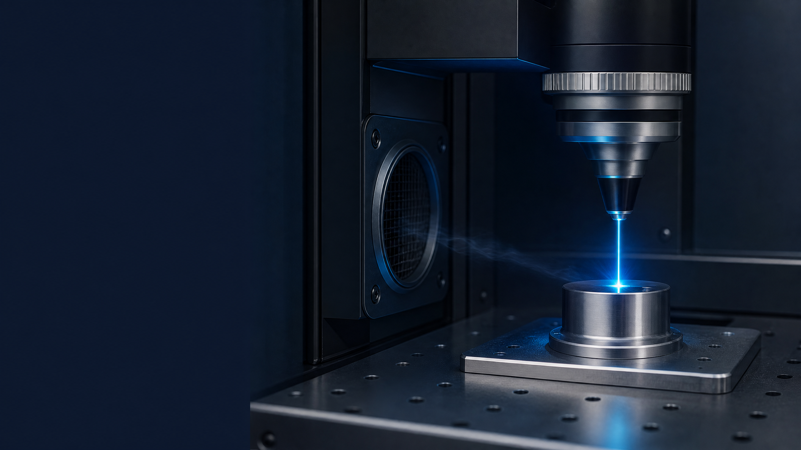
The beam, the material and the piece’s immediate environment form a single analysis zone. The proximity of capture then determines control of the flow.
READING THE EMISSION
The right question is not only "is there smoke?", but "what is it composed of, when is it produced and where should it be captured?".
Metals, minerals and organic materials can produce fine or ultrafine particles, oxides, soot and solid residues that must be characterized.
Thermal or photochemical transformation can release VOCs, aldehydes, combustion gases or molecular fragments depending on the material and process.
Fillers, adhesives, paints, coatings, plasticizers and finishes can strongly alter the emission profile of parts that appear otherwise similar.
FORMATION MECHANISMS
Technical assessment begins with the dominant interaction mechanism. NWS Laser expertise links the technology, the material and the intended function on the part.
Indicative reading: the final emission profile must be evaluated with regard to the actual material, surface treatments and production parameters.
CONTROL CHAIN
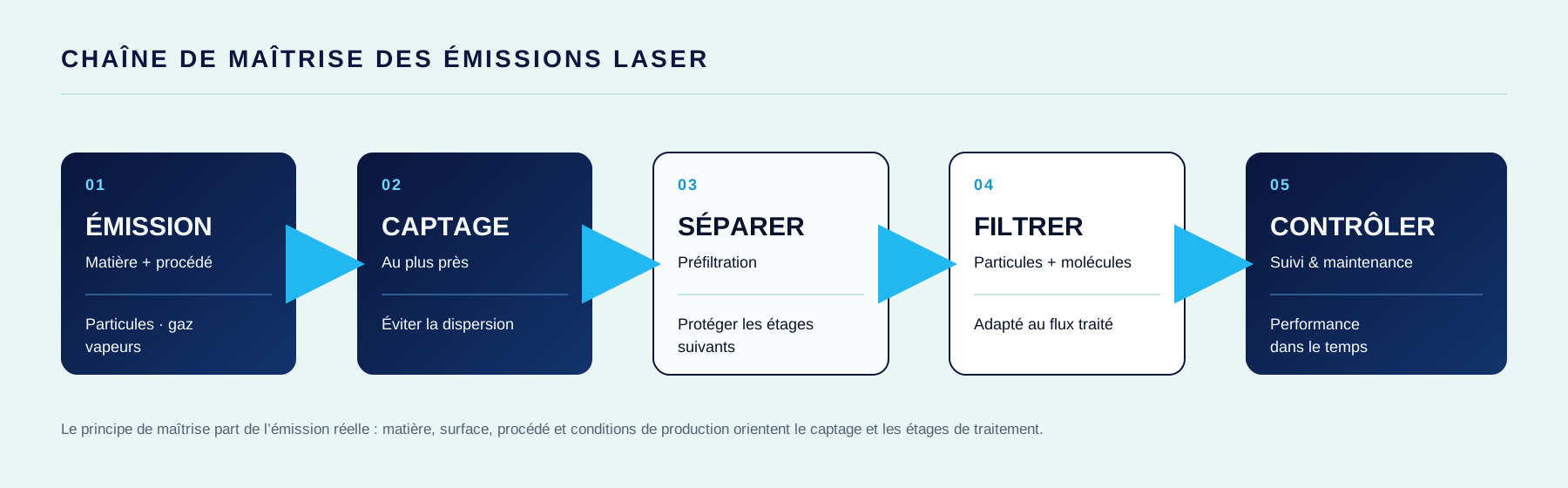
Air treatment is not limited to a standalone device. It begins at the point of generation and is organized as a chain of capture, separation, filtration and monitoring.
MATERIALS TO QUALIFY
METALS · COATINGS
Emissions can change with alloy composition, oxidation, surface treatment and contaminants. The finished part, not just the base metal, must be identified.
POLYMERS · COMPOSITES
Polymers do not all behave the same. Formulation, pigments, flame retardants and reinforcements must be included in the qualification.
ORGANIC MATERIALS
Organic materials generate smoke, dust and degradation compounds that vary with species, adhesives, tanning or dyeing.
SOURCE CAPTURE
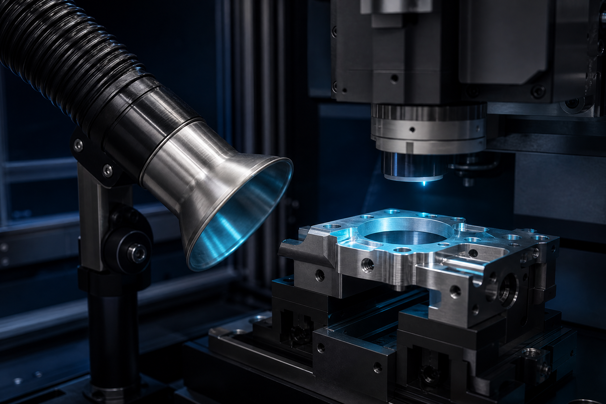
The extraction point should be placed as close as possible to the emission source. The opening, geometry, flow rate and work area must remain consistent with the process actually used.
CONTROL AT THE SOURCE
A control solution is built around the actual emission, its point of origin and the machine's usage conditions.
Material, surface treatment, adhesive, filler, coating and available supplier information.
Laser technology, power, frequency, speed, throughput, work area and enclosure level.
Capture should be planned where the emission originates, before it disperses into the production environment.
Separation and filtration stages are defined by the airflow; monitoring them ensures consistent performance.
PREVENTION FRAMEWORK
The project follows a chemical hazard prevention approach. In France and Switzerland, exposure assessment, collective risk control and process documentation must be tailored to the substances and work context involved.
Material datasheet, treatments, coatings and supplier information.
Point of generation, air movement and maintenance accessibility.
System monitoring and adjustment according to production changes.
LASER SMOKE & PARTICLE STUDY
Share the actual material, the laser process, production volume and shop constraints. NWS Laser will help you qualify the emission risk and define the capture concept to investigate.