Separate cutting and engraving settings
Cutting and engraving do not use the same settings. Speed, power, focus and number of passes are determined separately based on the part geometry and the desired result.
CUTTING · ENGRAVING · MINIATURE TRACEABILITY · CO₂ RF
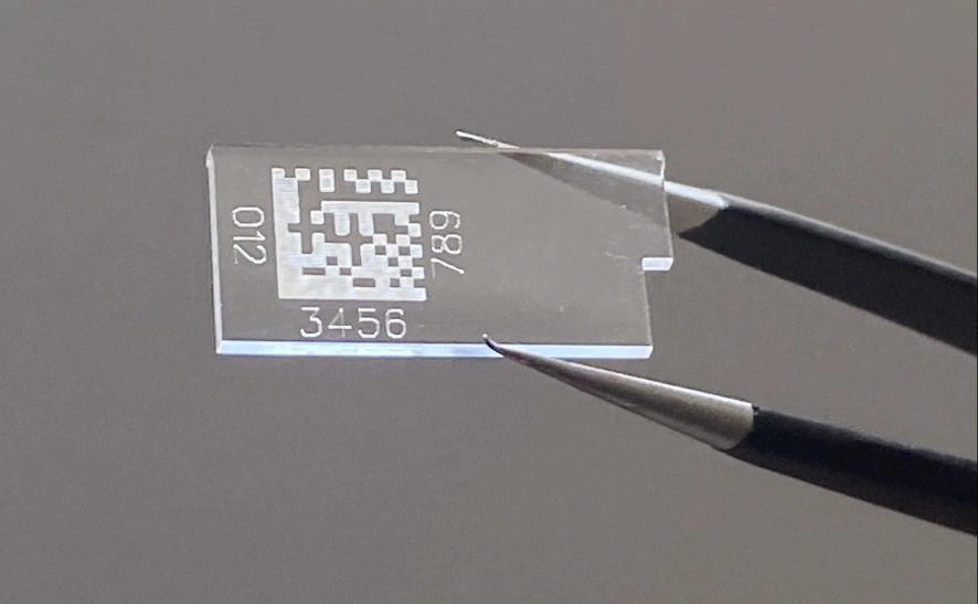
A transparent CR39 part cut and engraved with a miniature DataMatrix, on a CUT-X PRO using CO₂ RF technology.
This application combines cutting and engraving of a CR39 part with marking of a miniature DataMatrix. The engraved characters and the code are defined according to the information to be inscribed and the available area on the part.
The CUT-X PRO uses a CO₂ source with radio-frequency excitation, suited to operations on non-metallic materials. Cut and engraving parameters are adjusted separately and then qualified on an actual CR39 sample: speed, power, focus, part holding and DataMatrix reading conditions must be defined through testing, without presuming optical appearance or edge condition.
CUTTING, ENGRAVING AND CODE ON THE SAME PART
Cutting and engraving do not use the same settings. Speed, power, focus and number of passes are determined separately based on the part geometry and the desired result.
An appropriate fixturing limits part movement without obstructing cutting and engraving areas. Holding, working distance and focus are qualified on the actual CR39 used, checking results after testing.
The code content, its placement area and the reread conditions must be defined together. Readability is verified with the reader and lighting intended for production; the photograph alone does not constitute validation.
On an annotated drawing, distinguish the contour to be cut, the characters and the proposed location for the DataMatrix. Identify the relevant face and the expected reading direction once the part is in its position of use. Which surfaces must remain free of inscriptions? Which reference points will be used to locate the marking relative to the final contour?
Specify whether the supplied sample corresponds to the part before cutting or to its final geometry. Report any differences from the intended part. The CUT-X PRO presented for this application provides the machine context for the discussion, without prejudging the validation of your geometry.
In the file, separately identify the elements intended for cutting and those intended for engraving. Indicate the units, scale and design version. If several variants exist, designate the one to be examined rather than leaving a choice between files with similar names.
For the DataMatrix, provide an exact example of the expected string and specify the fixed or variable elements. Must spaces, separators and leading zeros be preserved? Do the visible characters repeat all the data in the code or only some of them? These choices remain to be agreed before the trial.
Distinguish the visual assessment of the engraving, the inspection of the contour and the verification of the data read back. For each point, indicate who decides on acceptance and by which method. An observation without a defined threshold must remain a point for discussion, rather than becoming assumed compliance.
Associate each sample with a reference and the corresponding file version. Include an annotated view when the orientation or location remains ambiguous. List the open questions and separate mandatory requirements from presentation preferences.
Technical expertise can be the starting point for discussing these decisions. In your application study request, name the person authorised to validate the criteria and report any information that is still missing. The trial conditions and the precautions specific to your part remain to be agreed with NWS Laser.
APPLICATION STUDY
Send the part or a sample, the geometry to be cut, the characters to be engraved, the DataMatrix data and the reading conditions. The NWS Laser team will prepare a trial on CUT-X PRO with CO₂ RF technology adapted to your application.