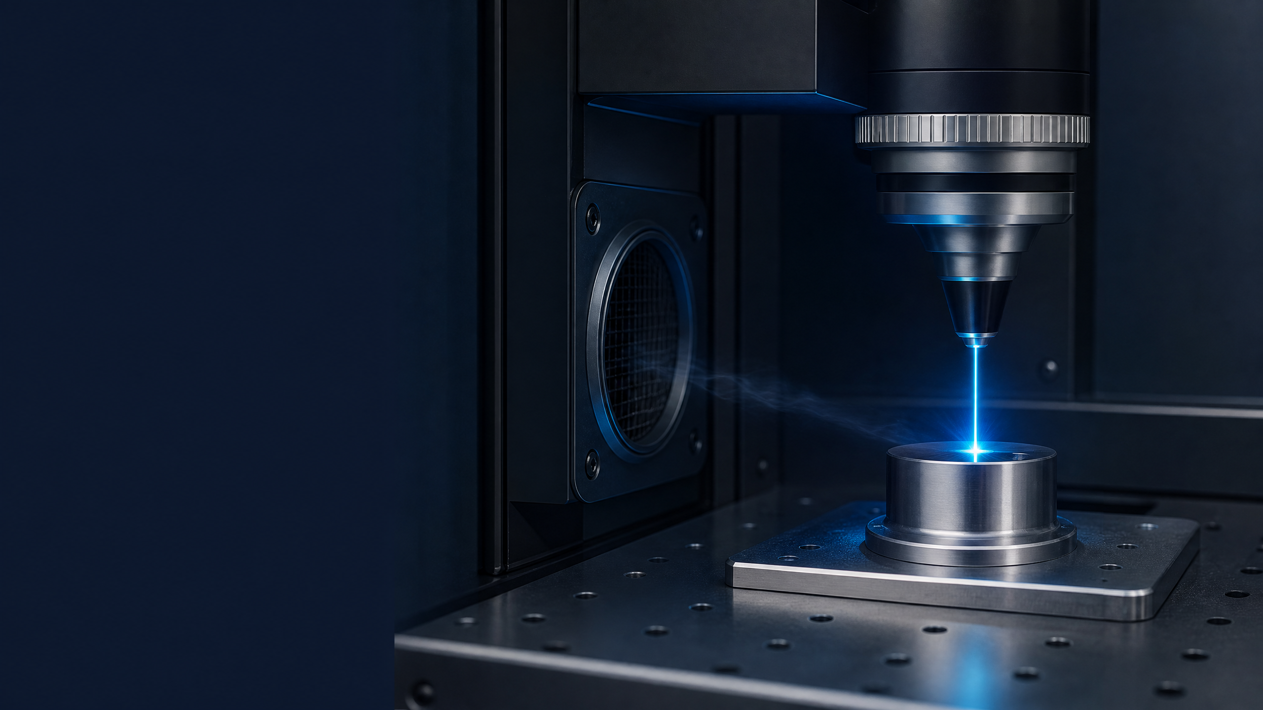
Laser interaction
Contrast, depth, surface condition and emissions depend on wavelength, pulse regime, material and the actual parameters used.
NWS LASER EXPERTISE · CONTROLLED INTEGRATION
An integration sheet to pair a laser marking cell with emission capture and filtration adapted to medical, pharmaceutical and cleanroom environments.
THE UNIT
In a medical, pharmaceutical or controlled environment, the laser, enclosure, capture and extractor form a single system to be qualified. The extractor helps control emissions; it does not replace laser safety, close-capture at the part, or zone qualification.
THE THREE PILLARS
The choice of source, cell architecture and air management must be qualified together based on the material, production parameters and site requirements.
Contrast, depth, surface condition and emissions depend on wavelength, pulse regime, material and the actual parameters used.
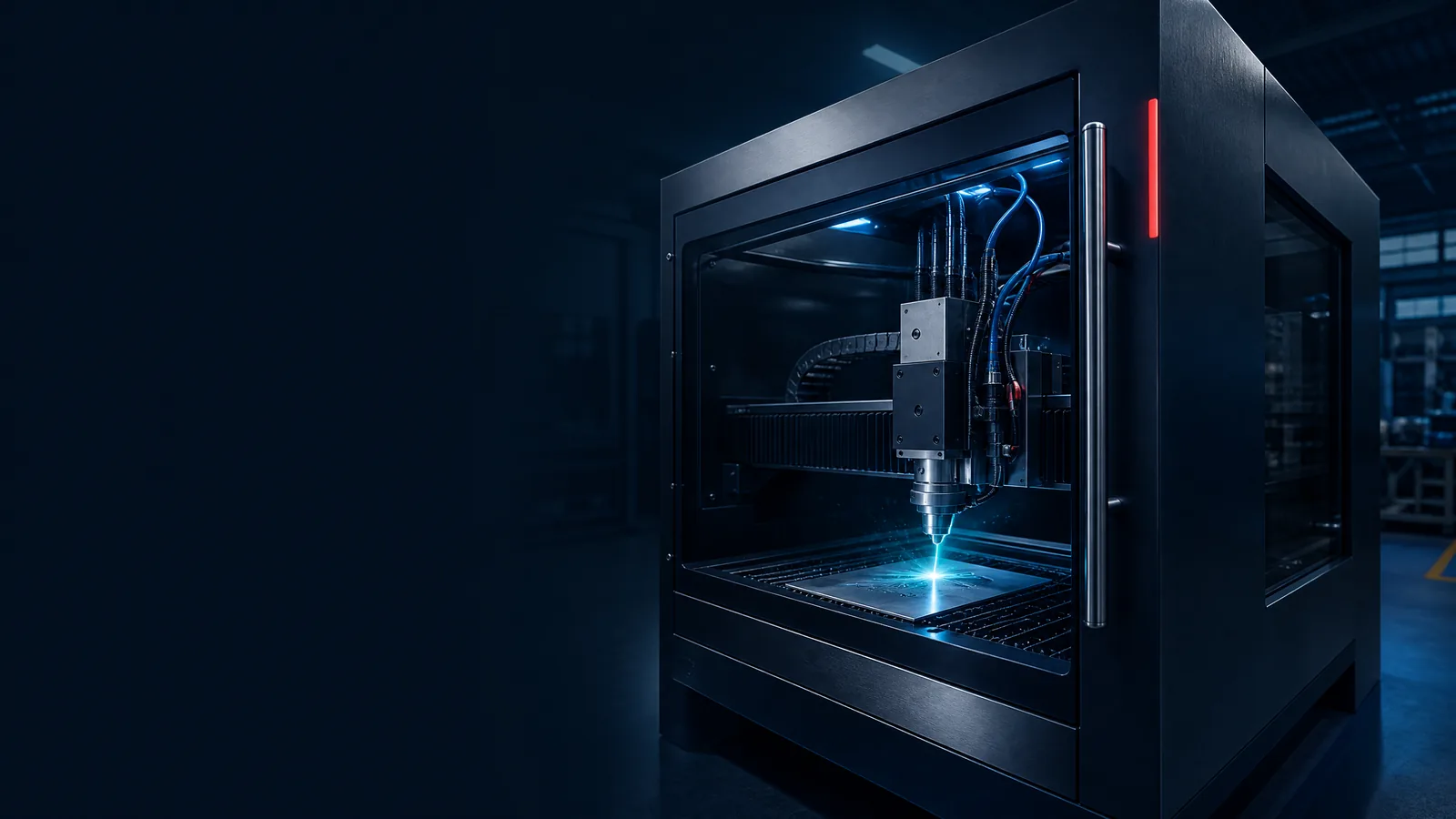
A closed, interlocked and serviceable cell protects access to the beam while providing a coherent volume for part positioning and capture.
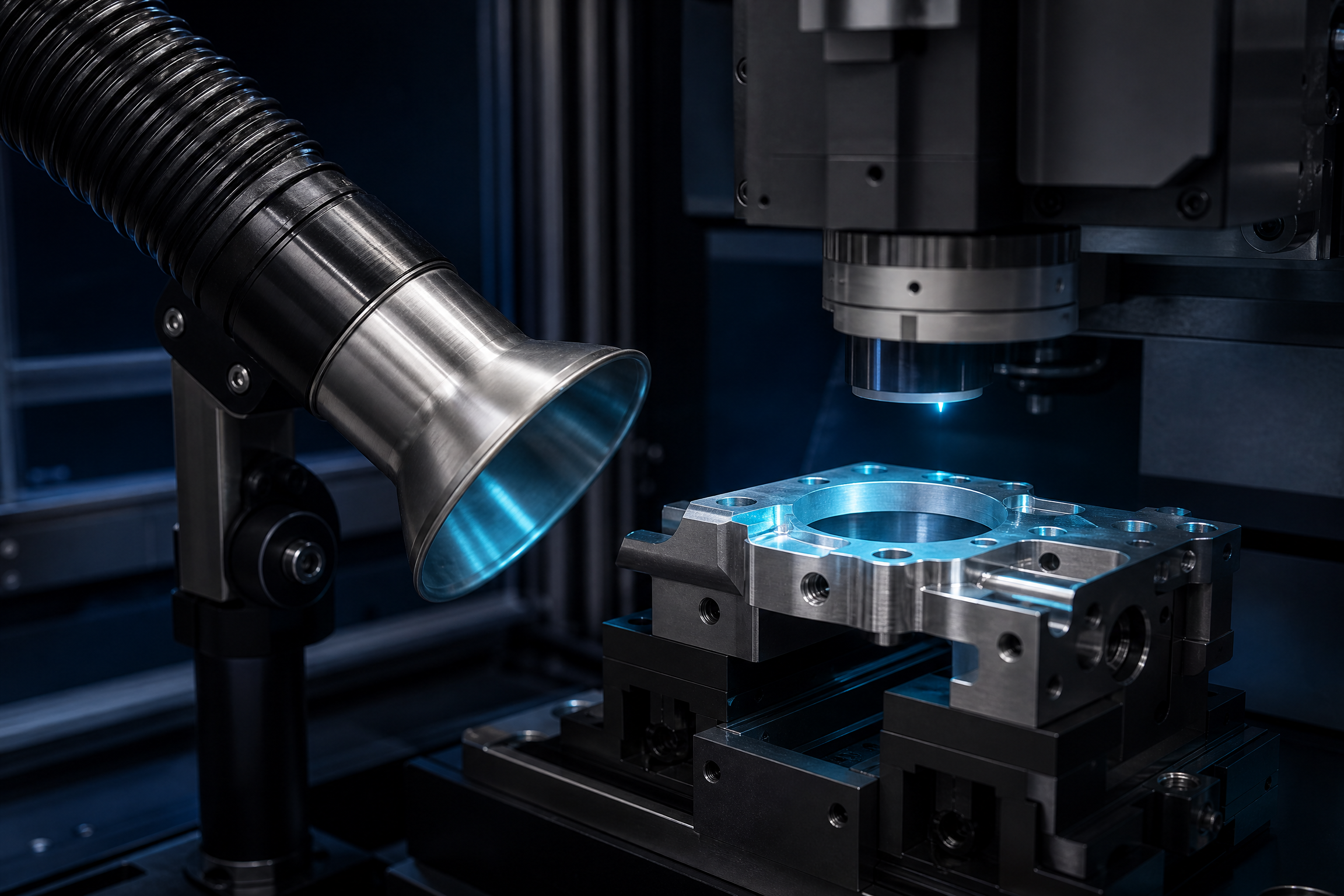
The nozzle, plenum and ductwork should be designed as close to the plume as possible without obstructing optics, focal plane, visibility or critical zone flows.
INTEGRATION ARCHITECTURE
Integration flow is not just “connecting an extractor.” Every interface must be documented: safety, airflow, controls, maintenance, materials and qualification requirements.
Configuration decisions are confirmed with quality management, the HSE team and, when required, the site HVAC operator.
Class 4 laser module integrated into a secured final machine.
Enclosure, interlocks, part fixturing, axes and signaling adapted to the process.
Intercepting the plume at the laser–material interaction point.
Filtration, condition monitoring and alert forwarding to the cell.
CHOOSE THE PROCESS
Wavelengths and final choice depend on the material, grade, additives and actual production parameters.
CELL & EXTRACTION
The IK-SERIES range provides an integrable laser base; the final cell, its protections and automation are the responsibility of the qualified manufacturer or integrator. The AD Oracle Pro OS is a standalone extractor associated with a specific machine or cell, to be distinguished from a centralized installation.
SEE THE IK-SERIES RANGE↗Choose wavelength and pulse regime according to the material, desired effect, emissions and controlled-environment requirements.
The final machine must combine an enclosure, interlocks, signaling, maintenance access and a risk analysis.
System status in real time, configurable alerts and escalation strategy to the PLC.
The reversible housing and duct circuit are validated according to the HVAC strategy and the site.
CLEANROOM CONFIGURATION
ISO 14644-1 classification concerns the concentration of airborne particles. It does not qualify the chemical or microbiological nature of contaminants, nor the overall compliance of the installation.
An architecture combining particulate filtration and chemical treatment according to the documented standard configuration.
The final HEPA on the exhaust side retains any carbon fines before they return to the controlled environment and serves as a final particulate barrier in this dedicated configuration.
Effective filtration alone is not sufficient to declare a compliant cleanroom. Layout, airflow, materials, maintenance and the site's environmental qualification remain decisive.
QUALIFICATION & ACCEPTANCE
Acceptance is built with the customer around a defined worst case: part, material, cycle, emission conditions, safety and environmental requirements.
Laser and extractor references, filter configuration, connections, software versions and labeling.
Interlocks, emergency stop, signaling, extraction fault and restart conditions.
Observe the plume under representative conditions and verify absence of backflow outside the captured zone.
Contrast, legibility, surface finish and environmental controls specified by the site protocol.
MAINTENANCE & TRACEABILITY
Filters, ducting and cell-extractor interfaces follow an approved procedure. Their maintenance must prevent re-entrainment of dust, record the operations and trigger a risk review when the material, settings or capture system change.
REFERENCES & LIMITATIONS
This sheet is intended as an integration aid. It does not constitute a complete chemical risk assessment, GMP qualification, a declaration of conformity to ISO 14644, or material compatibility validation. Manufacturer data and site requirements take precedence.
INTEGRATION STUDY
Provide the material and its grade, the planned parameters, throughput, layout, zone requirements and exhaust constraints. NWS Laser will help define the appropriate laser, capture and extraction.